Dual Concentric Rotary Encoders
The frequency adjustment controls for the radio equipment are implemented using rotary encoders. In many case there is a requirement for a dual concentric type device, in order that an outer knob can be used for course control and an inner knob can be used for fine control.
Incremental rotary encoders provide a pair of out of phase digital signals that allow determination of both the speed and direction of a shafts rotation.

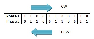
The quadrature nature of the two signals contains directional information. The bit 2 bit binary pattern produced will be different depending on the direction of rotation.

As can be seen from the 2 bit number sequence, only one bit ever changes at a time. When the encoder is turning CW the pattern will be 01,00,10,11 and when turning CCW the pattern is 01,11,10,00. This sequence is commonly known as Gray Code.
An additional attribute of the rotary encoder is the detent. The detent is a position to which the encoder will settle between rotation steps, for example there may be 16 detents for each 360 degrees of rotation.
Implenetation
The electronic interface to the rotary encoder is achieved using the Master Card supplied by OpenCockpits. This interface has the ability to read Gray Type encoders directly BUT there is an additional requirement of this interface, which causes us issues.
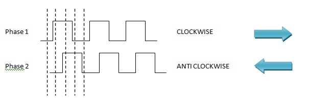
The encoder as well as being Gray Type, must also be ¼ cycle per detent, as shown
The clockwise output from the encoder from the above would be 00 at detent 1, 10 at detent 2, 11 at detent 3 and 01 at detent 4..

The clockwise output from the encoder from the above would be 00 at detent 1, 10 at detent 2, 11 at detent 3 and 01 at detent 4.
It is possible to source low cost encoders of this type from both Bourns and CTS, but they are not of the concentric type. One possible solution is to construct some type of mechanical solution by combining two single devices:


Concentric Rotary Encoder Implementation
After much research a small dual concentric rotary encoder was found. The devices are manufactured by ELMA as the E37.

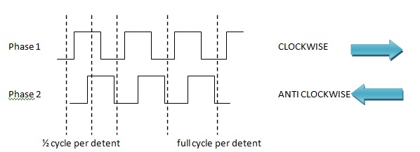
These devices although of Gray Type, they were not ¼ cycle per detent. The available options were ½ cycle per detent or full cycle per detent. The output formats are shown
These encoders will not interface directly to the Master Card. OpenCockpits do supply an interface card which can be used to connect four Gray Type encoders to the Master Card inputs.

OpenCockpits Encoder II Interface Card
This interface uses a PIC microcontroller to interface four encoders to the Master Card.
On further investigation it was found that it would only work with full cycle per detent type devices. It was decided to try and modify the PIC code to cater for the ½ cycle per detent type.
PIC Code
The Encoder II card uses PIC16F876 micro-controller device. The code was downloaded as a HEX file from the PIC using a PIC programmer device, this code was then run through a disassembler to produce a symbolic list file, which was in turn manually annotated and tidied up. A flow chart was generated from the assembler listing.

Original Operation
-
Initialise PORTC to read the four encoder inputs
- Initialise PORTB as outputs to be connected to the Master Card
- Enter a loop waiting for the encoder outputs to change
- If CW rotation set b0 = 0 and toggle b1 on each step
- If CCW rotation set b0 = 1 and toggle b1 on each step
- After either 4 or 5 enter a loop waiting for both encoder outputs to be 0, signifying that the encoder has reached the detent position.
Step 6 relies of the encoder being a full cycle per detent type as both encoder outputs are 0 at each detent position.
Modified Operation
The difference between the full and ½ cycle devices is that for the full type both outputs are 0 at each detent position, while for the ½ cycle device both inputs are alternatively 0 and 1 at each detent position. Hence step 6 above will not work correctly for the ½ cycle per detent device type.
The solution is for step 6 to alternatively check for 0 and then 1 after each valid read of the encoder. The modified sequence is as follows:
- Initialise PORTC to read the four encoder inputs
- Initialise PORTB as outputs to be connected to the Master Card
- Initialise a mask which will be used to XOR the encoder inputs. The initial value will be 00 or 11 depending on the initial detent position of the encoder
- Enter a loop waiting for the encoder outputs to change. The encoder outputs are XORd with the mask. If the mask is 11 the encoder outputs are inverted, if the mask is 00 the encoder outputs remain unchanged.
- If CW rotation set b0 = 0 and toggle b1 on each step. XOR current mask value with 11 to invert
- If CCW rotation set b0 = 1 and toggle b1 on each step. XOR current mask value with 11 to invert
- After either 5 or 6 enter a loop waiting for both encoder outputs to be either 00 or 11 depending on the current mask value, signifying that the encoder has reached the detent position.
Flow Chart

Assembler Listing For Modified Version
;*********************************************************************
;* Title : My Project
;* Version : 1.0
;* Author : Terry Adams
;* Pic Type : PIC16F876
;* Date : 19/05/2009
;* Description :
;* Modified for Opencockpits Encoder II card
;* original designed for 'Full Cycle per Detent' type rotary encoder
;* this version modified to work with 'Half Cycle per Detent' type
;* Clock : 4.0 MHZ
;* Clock Type : XTAL
;*********************************************************************
include "n:\K8048\Include_files\P16F876.INC" ;PIC Include File
LIST P=PIC16F876 ;PIC Include File
ORG 0x0 ;Start Function
goto init
nop
ORG 0x4 ;Interupt routine
goto push_int
;***********************************************
;NOTE - interupts not used, encoders are polled
;***********************************************
push_int ;start interupt routine, save Registers
movwf 0x70 ;save W at 0x70
movf STATUS,W ;move STSTUS to W
movwf 0x76 ;save STATUS at 0x76
movf PCLATH,W ;move prog counter to W
movwf 0x77 ;save prog counter at 0x77
movf FSR,W ;move FSR to W
movwf 0x78 ;save FSR at 0x78
btfss INTCON,INTF ;check inturupt reg
goto pop_int
nop
pop_int ;restore registers on exit from interupt
clrf STATUS ;clear STATUS
movf 0x78,W ;get FSR from store
movwf FSR ;restore FSR
movf 0x77,W ;get prog counter from store
movwf PCLATH ;restore prog counter
movf 0x76,W ;get STATUS from store
movwf STATUS ;restore STATUS
swapf 0x70,F ;restore W without changing bits
swapf 0x70,W
retfie ;return from interupt
init ;Initialze the PIC ports and registers
bcf STATUS,RP0 ;switch to bank 0
bcf STATUS,RP1
clrf PORTA
clrf PORTB
clrf PORTC
bsf STATUS,RP0 ;switch to bank 1
bcf STATUS,RP1
clrf TRISB ;RB0-RB7 as outputs
clrf TRISA ;RA0-RA7 as outputs
movlw B'11111111' ;RC0-RC7 as inputs
movwf TRISC
movlw B'110' ;port A as digital inputs
movwf ADCON1
bcf STATUS,RP0 ;switch to bank 0
bcf STATUS,RP1
clrf PORTB
clrf PORTA
movlw B'00000000' ;clear temp counters
movwf 0x73
movwf 0x74
movwf 0x75
movwf 0x76 ;*added for mask to invert encoder pattern on*
;*alternate reads, for half cycle encoder type*
movlw B'11111111' ;set all outputs high
movwf PORTB
movf PORTC,W ;get the inital encoder state (either 00 or 11)
movwf 0x76 ;store current encoder pattern at 0x76
main_loop
movf PORTC,W ;get the current encoder status
movwf 0x72 ;store current encoder pattern at 0x72
movf 0x76,W ;invert 0x72 on alternat reads
xorwf 0x72,F ;invert if 0x76 is 1, don't invert if 0x76 is 0
;************************START CHECK ENC1*********************************
chk_enc1
btfss 0x75,1 ;test changed flag and loop until both bits
;are either 00 or 11 indicating at detent
goto chk_enc1_b0 ;go to read encoder value
btfsc 0x72,0 ;test b0 of 0x72
goto chk_enc2 ;not at detent so go to check next encoder
btfsc 0x72,1 ;test b1 of 0x72
goto chk_enc2 ;not at detend so go to check next encoder
bcf 0x75,1 ;at detent so clear changed flag
goto chk_enc2 ;done check next encoder
chk_enc1_b0 ;tests encoder bits 0 and 1
;if b0 = 0 and b1 = 1 then
;sets output b0 = 0 and toggles b1
;between low and high
btfsc 0x72,0 ;test b0 and skip next if zero
goto chk_enc1_b1 ;encoder b0 is high so check b1
btfss 0x72,1 ;test b1 and skip next if high
goto chk_enc2 ;b0 = 0 and b1 = 0, check next encoder
bcf PORTB,0 ;set bit 0 of PORTB to 0
movlw B'00000010'
xorwf PORTB,F ;toggle bit 1 of PORTB
movlw B'00000011' ;mask to toggle bits 0 and 1
xorwf 0x76,F ;toggle bits of 0x76
bsf 0x75,1 ;set changed flag
goto chk_enc2 ;done check next encoder
chk_enc1_b1 ;if b0 = 1 and b1 = 0 then
;set output b0 = 1 and toggle b1
btfsc 0x72,1 ;test b1 and skip next if zero
goto chk_enc2 ;b0 = 1 and b1 = 1, check next encoder
bsf PORTB,0 ;set bit 0 of PORTB to 1
movlw B'00000010'
xorwf PORTB,F ;toggle bit 1 of PORTB
movlw B'00000011' ;mask to toggle bits 0 and 1
xorwf 0x76,F ;toggle bits of 0x76
bsf 0x75,1 ;set changed flag
;*************************END CHECK ENC1**********************************
;
;************************START CHECK ENC2*********************************
chk_enc2
btfss 0x75,2
goto chk_enc2_b2
btfsc 0x72,2
goto chk_enc3
btfsc 0x72,3
goto chk_enc3
bcf 0x75,2
goto chk_enc3
chk_enc2_b2
btfsc 0x72,2
goto chk_enc2_b3
btfss 0x72,3
goto chk_enc3
bcf PORTB,2 ;set bit 2 of PORTB to 0
movlw B'00001000'
xorwf PORTB,F ;toggle bit 3 of PORTB
movlw B'00001100' ;mask to toggle bits 3 and 2
xorwf 0x76,F ;toggle bits of 0x76
bsf 0x75,2
goto chk_enc3
chk_enc2_b3
btfsc 0x72,3
goto chk_enc3
bsf PORTB,2 ;set bit 2 of PORTB to 1
movlw B'00001000'
xorwf PORTB,F ;toggle bit 3 of PORTB
movlw B'00001100' ;mask to toggle bits 3 and 2
xorwf 0x76,F ;toggle bits of 0x76
bsf 0x75,2
;*************************END CHECK ENC2**********************************
;
;************************START CHECK ENC3*********************************
chk_enc3
btfss 0x75,3
goto chk_enc3_b4
btfsc 0x72,4
goto chk_enc4
btfsc 0x72,5
goto chk_enc4
bcf 0x75,3
goto chk_enc4
chk_enc3_b4
btfsc 0x72,4
goto chk_enc3_b5
btfss 0x72,5
goto chk_enc4
bcf PORTB,4 ;set bit 4 of PORTB to 0
movlw B'00100000'
xorwf PORTB,F ;toggle bit 5 of PORTB
movlw B'00110000' ;mask to toggle bits 5 and 4
xorwf 0x76,F ;toggle bits of 0x76
bsf 0x75,3
goto chk_enc4
chk_enc3_b5
btfsc 0x72,5
goto chk_enc4
bsf PORTB,4 ;set bit 4 of PORTB to 1
movlw B'00100000'
xorwf PORTB,F ;toggle bit 5 of PORTB
movlw B'00110000' ;mask to toggle bits 5 and 4
xorwf 0x76,F ;toggle bits of 0x76
bsf 0x75,3
;*************************END CHECK ENC3**********************************
;
;************************START CHECK ENC4*********************************
chk_enc4 btfss 0x75,4
goto chk_enc4_b6
btfsc 0x72,6
goto goto_main_loop
btfsc 0x72,7
goto goto_main_loop
bcf 0x75,4
goto goto_main_loop
chk_enc4_b6
btfsc 0x72,6
goto chk_enc4_b7
btfss 0x72,7
goto goto_main_loop
bcf PORTB,6 ;set bit 6 of PORTB to 0
movlw B'10000000'
xorwf PORTB,F ;toggle bit 7 of PORTB
movlw B'11000000' ;mask to toggle bits 7 and 6
xorwf 0x76,F ;toggle bits of 0x76
bsf 0x75,4
goto goto_main_loop
chk_enc4_b7
btfsc 0x72,7
goto goto_main_loop
bsf PORTB,6 ;set bit 6 of PORTB to 1
movlw B'10000000'
xorwf PORTB,F ;toggle bit 7 of PORTB
movlw B'11000000' ;mask to toggle bits 7 and 6
xorwf 0x76,F ;toggle bits of 0x76
bsf 0x75,4
;*************************END CHECK ENC4**********************************
goto_main_loop
goto main_loop
END
HEX Files
The ZIP files contains three HEX images, one for a quarter cycle per detent version, one for a half cycle per detent version and one for a full cycle per detent version.
They can be copied to the OpenCockpits Encoder II card PIC 16F876 with a suitable PIC programmer.
- encoderhexfiles.zip
- PIC 16F876 HEX Images
