Introduction
Radio Stacks are available from a number of suppliers in various forms. Both Simkits and Flight Illusion produce complete Radio Stacks suitable for the Cessna 172 but they are expensive, for example the Simkits complete Radio Stack is approximately 3,500 Euros.
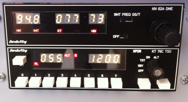
It was decided to try and build a Radio Stack on a modular basis, the construction took a number of years and was modelled on the Bendix King Silver Crown unit.
The front panels were manufactured by in 3mm aluminium by Schaeffer AG, who are based in Germany Their 'free Font Panel Designer software was used to design the panels.
The inital development used interface circuit boards from OpenCockpits who are based in Spain, they provide a scriptting software packaged called SIOC, which is used to interface the hardware to the flight simulator via the FSUIPC add-on from Peter Dowson.
In the final version of the Radio Stack, the OpenCockpits interfaces were replaced by micro-controller based units.
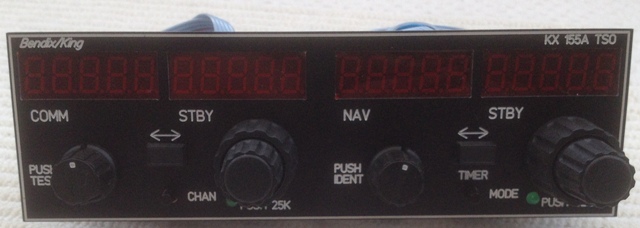
Transceiver
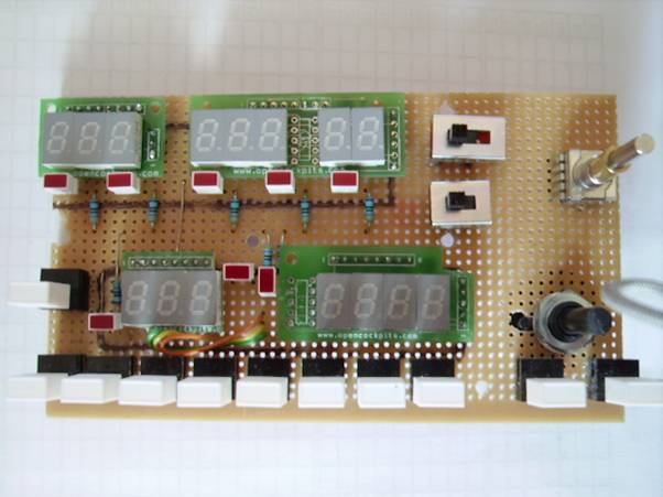
Version 1
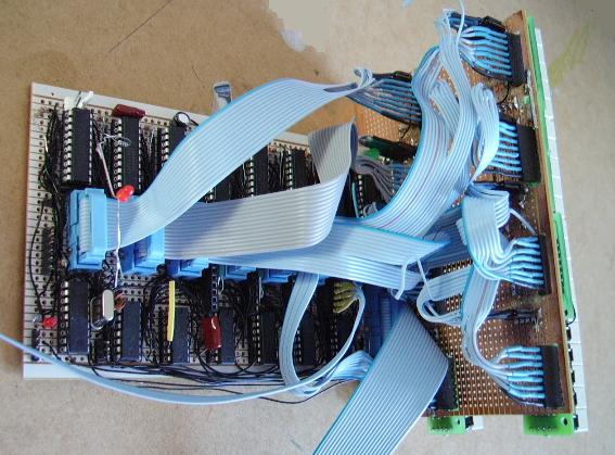
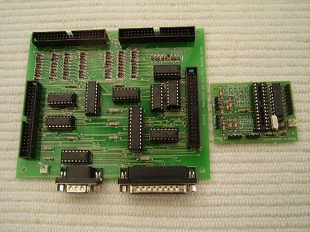
The first version was constructed as a dual unit, using OpenCockpits interfaces including their 7 segment display mounts, 7 segment display driver board and a modified version of their encoder interface, adapted to work with the ELMA E37 dual concentric rotary encoder.
The biggest shortcomings with this version was that the displays were very dim due to the multiplexing nature of the OpenCockpits Display II interface and the large amount of interconnection wiring between the 7 segment display modules.
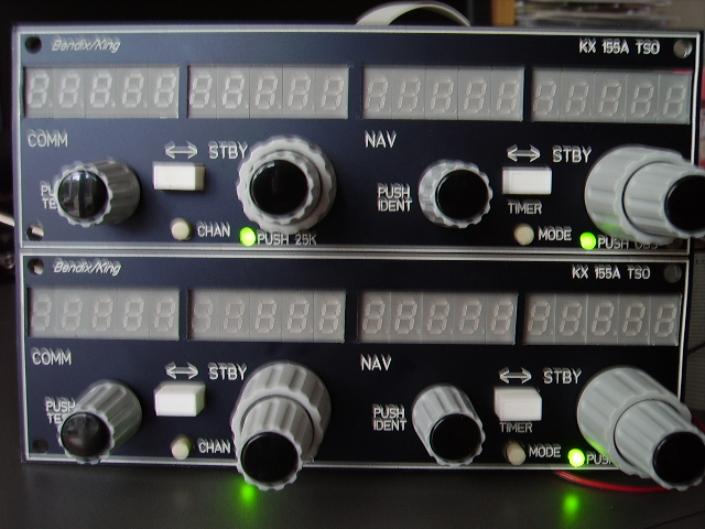
Version 2
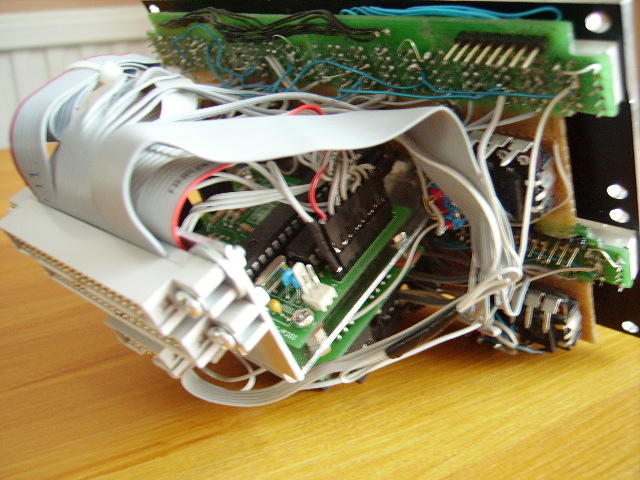
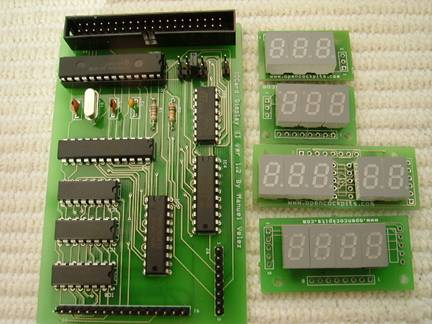
The second version retained the OpenCockpits 7 segment display mounts, but Motorola MC14489 display drivers were used to interface to the 7 segment displays. The unit was again constructed as a dual module.
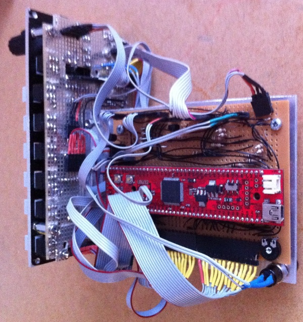
The firmware to control the unit was incorporated into the AutoPilots UBW32 PIC based controller board.
A separate PIC 16F88 micro-controller was used to control the MC14489 display drivers.
This version worked satisfactorily, although the display electronics and interconnecting wiring was still fairly complex. When it became necessary to develop a single KX 155 module, a simpler solution was sought.
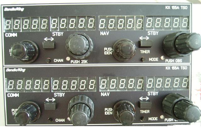
Version 3
The final version was constructed as a single unit. Five digit
7 segment displays were used inplace of the OpenCockpits display mounts. The now obsolere MC14489 display drivers were replaced by Maxim MAX7219 display drivers.
The unit was controlled by its own PIC 18F2550
micro-controller.
Version 2 and 3 of the transceiver included stored channel values and the ability to adjust the display brightness.
Documentation
- transceiverversion2.pdf
- Documentation for Version 2 of the Transceiver
- transceiverversion3.pdf
- Documentation for Version 3 of the Transceiver
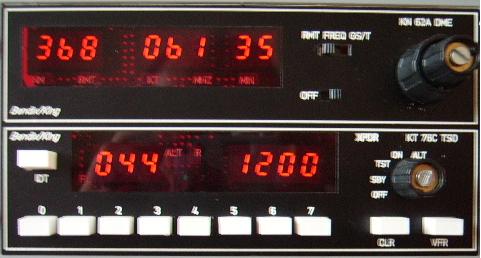
DME/Transponder
Version 1
The first version was constructed as a dual unit, using OpenCockpits interfaces including their 7 segment display mounts, 7 segment display driver board and a modified version of their encoder interface, adapted to work with the ELMA E37 dual concentric rotary encoder.
Version 2
In the second version the OpenCockpits interfaces were replaced, inparticular the
7 segment displays were found to be very dim when using the OpenCockpits
Dispaly II driver board. Maxim MAX7219 devices were selected as a replacement, connected to a micro-controller interface using the Serial Pheripheral Interface BUS (SPI).
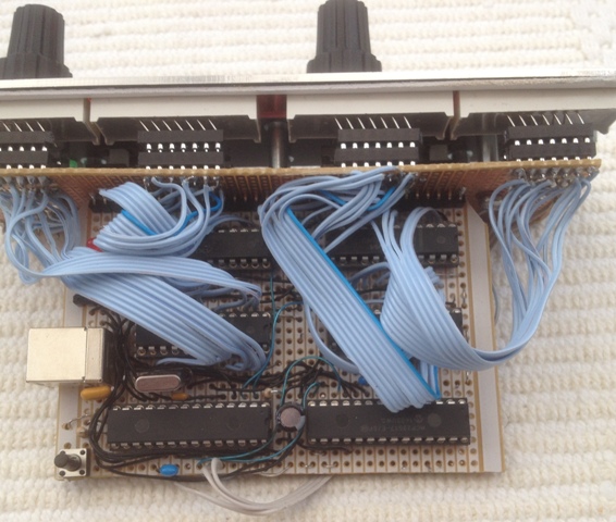
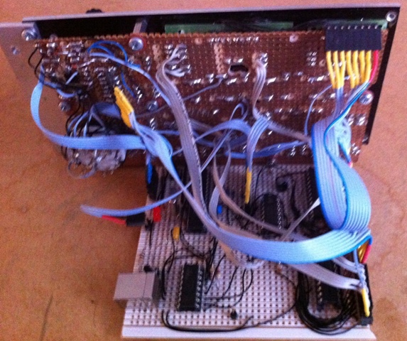
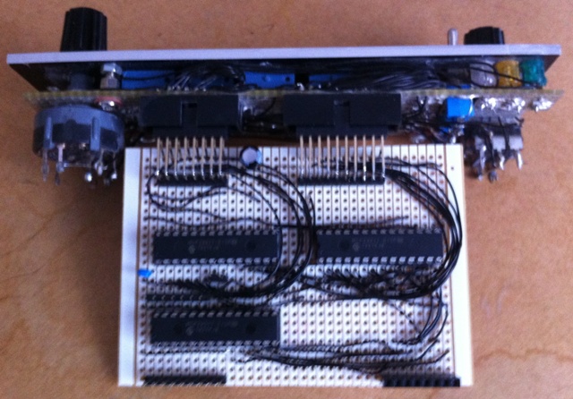
A second circuit board was added to the back side of the first. This circuit board was used to mount three Maxim MAX7219 display drivers and a PIC 18F2550
micro-controller chip, which was used to control both the DME and Transponder, as well as providing the USB interface.
PC side software was developed in Microsoft Visual C# to interface the unit to the Flight Simulator software.
Documentation
- transponderanddistancemeasuringequipment-ii.pdf
- Distance Measuring Equipment and Transponder Documentation
Audio Panel
Version 1
The first version was constructed using OpenCockpits MasterCard to interface the switches and the LEDs.
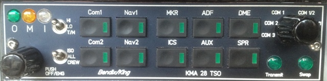
Version 2
The second version replaced the OpenCockpits interface by a connection to the existing PIC 18F2550 micro-controller used on the DME/Transponder module.
The connection was acheived by using three MCP23S17 input/output integrated circuits, connected to the DME/Transponder module using the SPI (Serial Peripheral Interface) bus.
Additional software was added to both the DME/Transponder module's PIC 18F2550 firmware and the PC side C# application software.
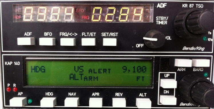
ADF/AutoPilot
The development of the AutoPilot was the main reason for the move away from OpenCockpits interface circuit boards. An LCD type display was selected as the only cost effective method for displaying the AutoPilot information. The OpenCockpits LCD interface is only capable of displaying numeric variable information (although it can display fixed alpha characters) and so was unsuitable for the AutoPilot.
The module was constructed as a dual unit,comprised of the ADF and the AutoPilot. A circuit board was used to mount the ADF 7 segment displays, the switches, LEDs, rotary encoders and the AutoPilot LCD display.
The ADF's 7 segment displays used were four digit serial devices, which use the SPI (Serial Peripheral Interface) protocol to connect to the micro-controller. The SPI interface is used on many occasions throughout the Radio Stack modules to enable inter-communication between hardware devices.
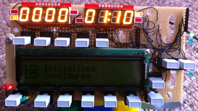
A UBW32 PIC based 32bit controller board was chosen for the module as it provided adequate input/output ports and had considerable processing capability. As the development was going to be an iterative process, it was decided to use a 'Real Time Operating System' as the basis for the software development. The free product 'FreeRTOS' was used to develop a seriers of parallel process for each function of the ADF and AutoPilot.
Documentation
- adfandautopilotdevelopment.pdf
- ADF and AutoPilot Documentation