Landing Gear Switch
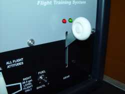
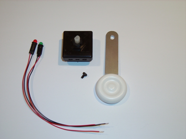
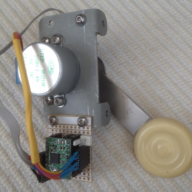
The most common variants Cessna 172 aircraft have fixed tricycle undercarriage, but as my flight simulator has an undercarriage switch/lever, I fly the RG type of 172, which has retractable landing gear. The landing gear switch was purchased from Simkits at some €250, which may be considered somewhat expensive for what is essentially a bracket, switch, metal lever with knob and two LEDs.
Interface and control is usually achieved using the Simlits Central Control Unit (CCU), but in my case I detect the switch state and control the LEDs from within the Transponder unit control software.
Although the unit works satisfactorily, the switch has the potential to be left in the wrong position on simulator start-up i.e. the landing gear is left in the retracted position when the simulator starts with the aircraft on the ground.
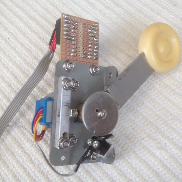
The initial idea was to use a solenoid to move the landing gear lever to the down position when the simulator was switched on. This approach was discarded due to the difficulties of obtaining a suitable solenoid and the restriction in space to fit the solenoid to the landing gear lever behind the simulator front panel.
The solution chosen was to use the experience gained with automating the elevator trim control using a stepper motor.
Documentation
- landinggearswitch.pdf
- Enter file download description here
Fuel Tank Switch
The Simkits fuel tank switch is an expensive option, when you consider it is no more than a three position switch and a knob, the estimated cost being £200 (including tax and shipping).
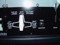
The actual switch has three positions, left, both and right, while the angle between each position is 90.
The switch provides two output signals the logic is 01, 10, 00 (left, both, right).
A simple single pole rotary switch is not capable of generating this output sequence. It would appear that Simkits have used something like the T9000 series switch from Arcoelectric, the logic for which can be derived from this diagram:
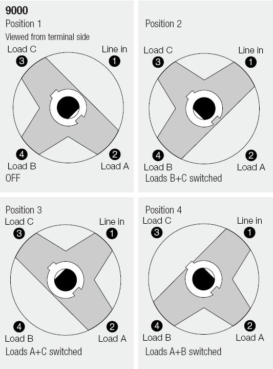
GND connected to (3)
Sig1 connected to (2)
Sig2 connected to (1)
Switch Position 1 Sig1 GND, Sig2 N/C (01)
Switch Position 2 Sig1 N/C, Sig2 GND (10)
Switch Position 3 Sig1 GND, Sig2 GND (00)
Switch Position 4 Not used
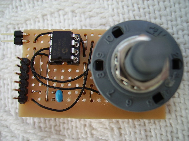
It was not possible to locate a UK distributor for the switch, the solution was to use a single pole, 3 position, 90 indexing switch and a MicroChip 12F508 microcontroller. The total cost of this implementation was £2, excluding the knob.
The switch was connected to inputs GP0 and GP1 such that in the left position both GP0 and GP1 were open-circuit and because these inputs have pull-up resistors, they would be both at logic 1. In the both position GP0 was pulled low and in the right position, GP1 was pulled low. Hence the logic output from the switch was 11, 01, 10 (left, both, right).
The software for the 12F508 was trivial, a simple lookup table to convert the physical switch inputs to the response expected by the Simkits interface and this was transferred to GP4 and GP5, configured as outputs.